Axis Drives
Millalyzer dynamic can optionally include models of servo motors and drive transmissions. These settings are available in millalyzer static, but have little effect on the results.
Detailed machine models can optionally be configured to account for the compliance of three linear axis drives. The contribution of motors and transmission elements to overall stiffness can be a significant factor for
- small belt-driven machines;
- standard moving-nut screw transmission with large pitch;
- small drive motors;
- motors geared using timing belts.
Including a model for the drive system will also provide warnings when the capacity of drives is exceeded: Motors and transmissions can only generate a limited amount of linear force, and a warning is issued when any of the mean cutting force components overcomes this limit.
Drive assignment
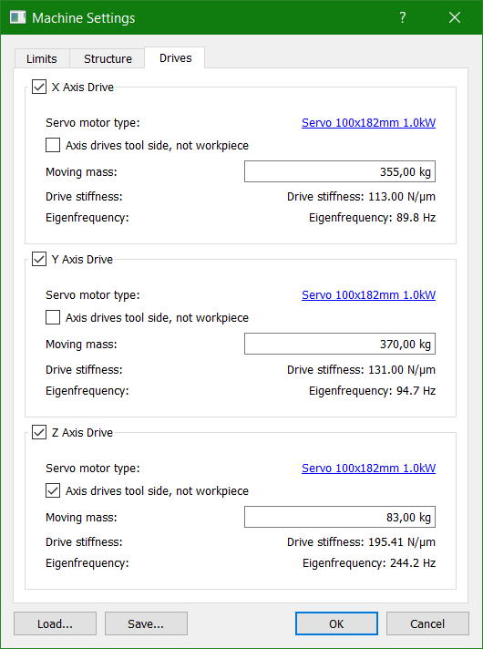 The overview screen shown under the Drives tab of the machine configuration dialog controls how the motor and transmission models are assigned to the machine axes.
Enable/disable
Each drive can be separately disabled. In this way, it is possible to perform an analysis with the drive system compliance eliminated, in order to test whether the drive has a significant effect on a particular problem such as chatter or excessive tool deflection.
Workpiece or tool side?
Each drive must be set to either move the workpiece/vise/stock side or the tool/spindle side of the machine. The example screen to the right is for a conventional vertical milling machine, where the workpiece is clamped onto a table that is driven by two cascaded drives in X and Y. The tool is mounted in a spindle head that which moves in the Z direction only.
Moving mass
The dynamic properties of a drive are determined by its compliance, which can be a function of feed, and the inertial mass that is accelerated by the linear axis. This mass included anything that is moving when the drive is active, such as nuts, cross-plates, machine tables, workholding fixtures and workpiece (in the case of a drive moving the workpiece). For the pre-defined models, the moving masses are adjusted to fit the underlying finite-element models, but you can adjust them to account for particularly heavy workpieces.
In order to configure the details of one particular drive, click on the underlined drive name (link), which opens the settings dialog shown below.
Drive settings
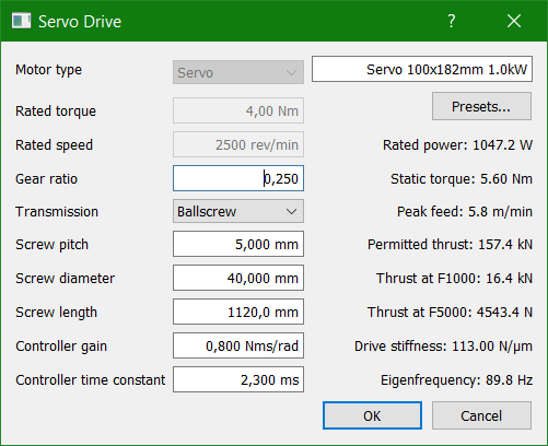 This dialog permits to change the details of the motor and transmission system used, and serves not only to generate data for the dynamic model (for chatter prediction), but also to allow evaluation of alternatives. For this purpose, a number of performance indicators are displayed on the right side of the dialog whenever the settings are modified.
Motor type
Small machines and CNC routers for woodwork are often driven entirely or partially by open-loop stepper motors. Such motors maintain their position in a manner that differs somewhat from closed-loop brushless servo motors, so that they are modelled differently here.
Stepper motors can be wired either for high low-speed torque (high holding torque constant [Nm/A], high coil resistance, high inductance) or better high-speed torque performance (lower static torque constant, low coil resistance, low inductance), all in the same form factor. Since these differences affect the dynamic performance significantly, it is recommended to choose one of the preset motor profiles. If none of the profiles is suitable, set the low-speed torque of the motor as its rated torque and the speed at which this value begins to drop substantially (typically between 60 and 500 rpm) as the rated speed.
Servo motors are used in closed-loop drive systems, where the voltage applied to the motor coils is controlled based on measured position and speed feedback. The apparent tangential stiffness of such systems is defined by the gain parameters of the speed control loop, which therefore need to be known.
The motor may be connected to a gear that usually reduces the speed (i.e. ratio < 1) of the drive and thus increases drive torque or thrust force. When the gear ratio is set to 1, a direct connection of motor and transmission by means of an elastic coupling is assumed; in most cases, such a coupling has a higher torsional stiffness than a timing belt gear at low ratio. A substantial gear ratio (0.25 or less) can increase effective stiffness if the motor side itself is very flexible.
When the transmission type is selected as a ball-screw or leadscrew, the effective gearing is determined by the screw pitch which specifies how far the axis moves per revolution. A similar parameter (translation per revolution) is available for linear belt- or rack-and-pinion drives. When computing the available feed forces, screw friction is accounted for according to data provided by manufacturers - these are for properly installed and well-lubricated devices; misalignment, contamination or insufficient lubrication will increase friction and reduce available thrust.
Screw diameter and length are used to compute the drive stiffness and permitted speed and thrust limits, because the operation of screws is subject to stability constraints.
Drive Analysis
The analysis values on the right side of the drive configuration dialog provide a quick evaluation of the current settings. This should allow the user to detect errors in the parameter settings or quickly discard drive options that are unsuitable for the intended application.
Permitted load and peak feed
Rotating screws are prone to wobble at a certain frequency which limits the speed at which a screw with given length and diameter can be operated. Furthermore, the product of screw speed and diameter is also limited for most types of ball-screws in order to ensure regular transitions of the balls in the recirculation channels. These two factors tend to control the peak feed speed for screw drives. For other types of transmissions, the feed limit is computed from the motor speed at which the torque drops to 10% of the rated value. Whenever these two limits in combination make it difficult to find a suitable screw configuration, a rack-and-pinion drive may be a better option.
As the force generated by the screw puts one side of the screw in compression, long and thin screws are susceptible to buckling. For short screws, the load rating of the ball nut tends to be the limit; this is often higher than the force that can be produced by the actuator.
Available thrust
The force that the transmission can generate accounts for known effects such as screw friction and gear efficiencies, but does assume good maintenance and correct assembly. Thrust values are computed for a low-to-moderate feed of 1 m/min (or 40 ipm) and a high feed value of 5 m/min (or 200 ipm), because drives with tight torque budgets will likely drop significantly over that range.
Stiffness and eigenfrequency
Finally, the analysis pane also displays the apparent drive stiffness as seen from the load/tool side, including the compliance of belt, screw or pinion, gear, coupling and motor. For some drive systems, this value will depend on feed (motor speed) and the simulation performed by millalyzer dynamic accounts for that. The eigenfrequency shown is determined by the inertia driven and the above stiffness.