Utilities
Two simple calculator tools can be found in the Utility menu. These only run in their respective window and are not connected to the main simulation.
Turning Calculator
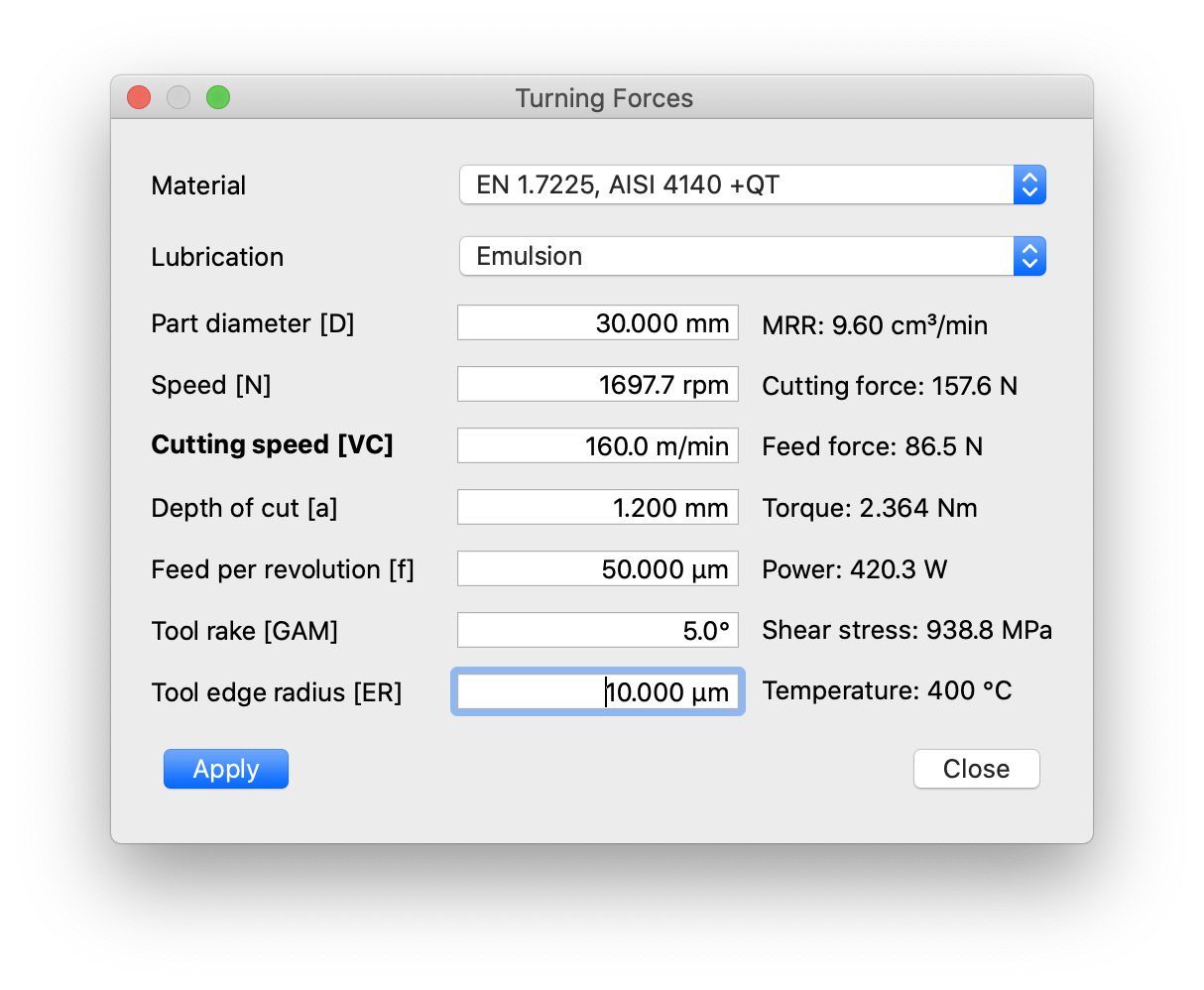 The turning calculator provides estimates of cutting- and feed-force, torque, mechanical power and conditions in the shear zone for a simplified turning problem. It may be used for both facing operations (radial feed) or axial turning (feed parallel to axis of rotation).
Material and lubrication/cooling type are selected in the same way as in the main simulation (but are not connected). The same material models as for milling are available for turning.
Part diameter is the diameter at which the cut is applied. For a facing operation, this value changes as the tool is fed into the part, so one value must be selected. For a conventional lathe that does not adjust speed with turning diameter, it may be best to set the initial (maximum) cutting diameter.
Speed can be adjusted either by entering the rotational speed [N] or the desired cutting speed [VC]. The other variable is then controlled by the last-changed setting, which is also displayed in bold.
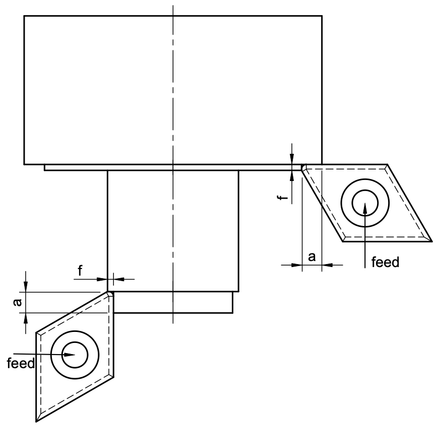 The meaning of depth of cut (a) depends on whether it is a facing operation (axial depth) or axial turning (radial depth); this is always the length of the engaged cutting edge. Feed is always specified as feed per revolution (f) and is the distance by which the tool is moved into the material during one workpiece revolution. This value corresponds to the un-cut chip thickness. See the image to the right for reference.
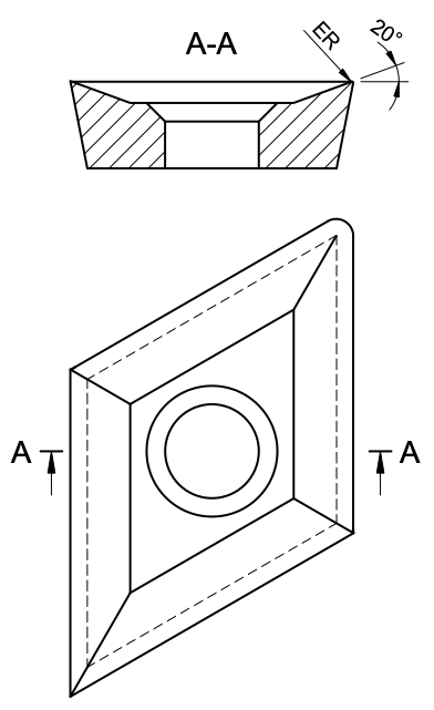
There are no detailed tool models for this simplified turning calculation. Instead, the tool is characterized by the effective tool rake angle (that is, the sum of tool-holder and insert rake) and the cutting edge radius. Note that this is the small radius of the edge facing the material, ‘ER’ in the image, not the in-plane corner radius of the insert.
| Material category | Rake | Edge radius | Comment |
|---|---|---|---|
| Wrought aluminium alloys | ≈ 20° | 1 - 5 µm | Ground & polished inserts |
| Steel & general purpose | ≈ 8° | 5 - 15 µm | Coated inserts |
| Hardened steel, HRSA | < 0° | 5 - 25 µm | Chamfered coated inserts |
 Finishing inserts have larger rake angles and smaller edge radius, but will not survive large feed-per-revolution values.
Please note that forces depend strongly on tool geometry, in particular the rake angle. The cutting force is the force component in circumferential direction, which increases quickly with decreasing rake angle. A positive feed force resists the feed motion (i.e. pushes the insert out of the workpiece). It can become negative for very large positive rake angles.
Drilling Calculator
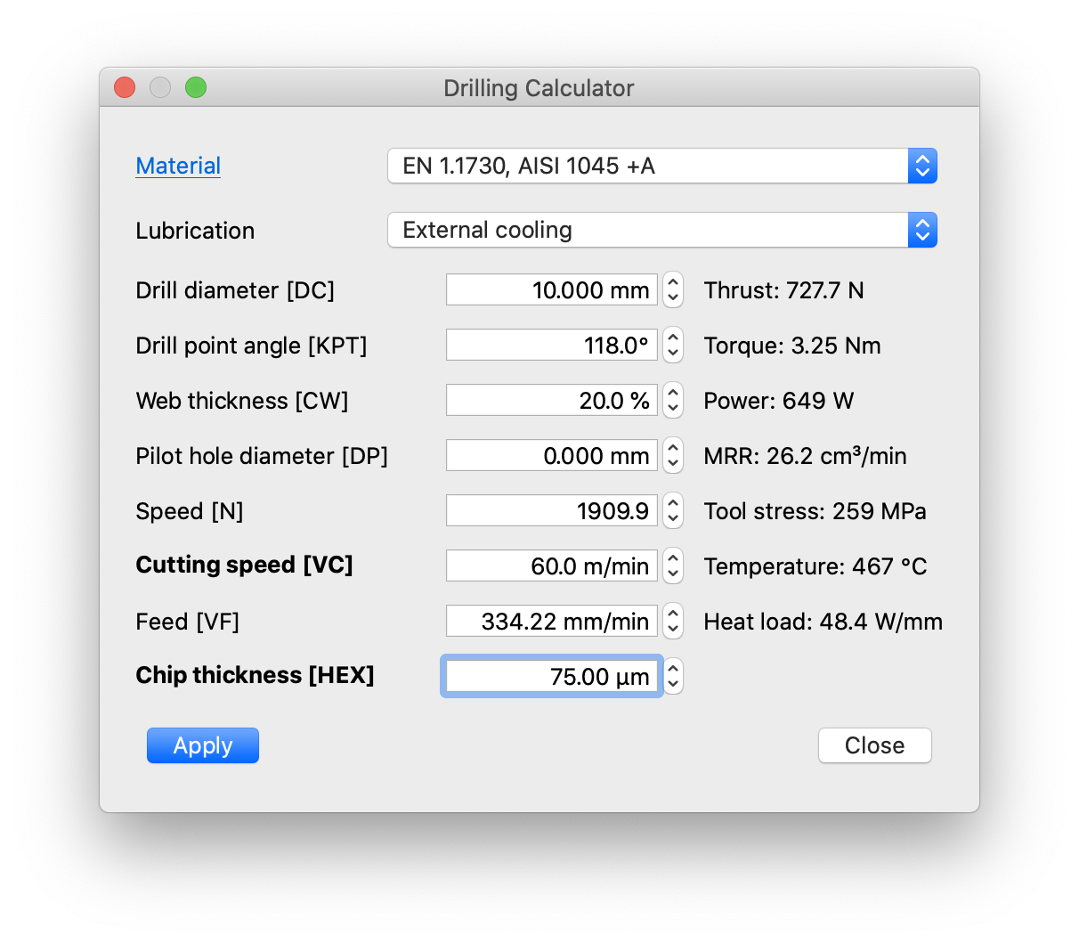 This simple tool can be used to estimate force and torque needed for drilling. Again, the workpiece material is selected in the same way as in the main simulation. Effective lubrication during drilling more or less requires that the drill is equipped with internal (spiral) cooling channels which allow the lubricating agent to be injected close to the cutting edges. Such drills are rather more expensive than solid tools, which can only be cooled externally, which is much less effective once a certain hole depth is reached.
Aside from the obvious drill diameter, there is also the option to specify a pilot hole diameter. Set this value to zero for drilling into solid material. Pilot holes can reduce the thrust force very significantly if there are larger than the drill core, as that avoids engagement of the chisel edge.
The drill geometry is defined by the tip angle and the core thickness; more parameters will be made available at a later stage. The tip angle (or point angle) is often 118°, but can be larger as well. A core or web thickness of around 20% is common. A smaller core thickness makes the drill weaker (higher tool stress) but reduces the chisel width and hence the thrust force and allows for larger chip gullets. The drill helix angle is currently fixed at 30°.
In the same way as in the main (milling) operation setup, the drill speed can be defined either by selecting the peripheral cutting speed VC or the rotational speed N directly. The corresponding property will be set accordingly and the controlling variable is labelled in bold. The same holds for feed which can be set via vertical feed rate VF or effective chip thickness HEX (which takes the point angle into account).
Drive Calculator
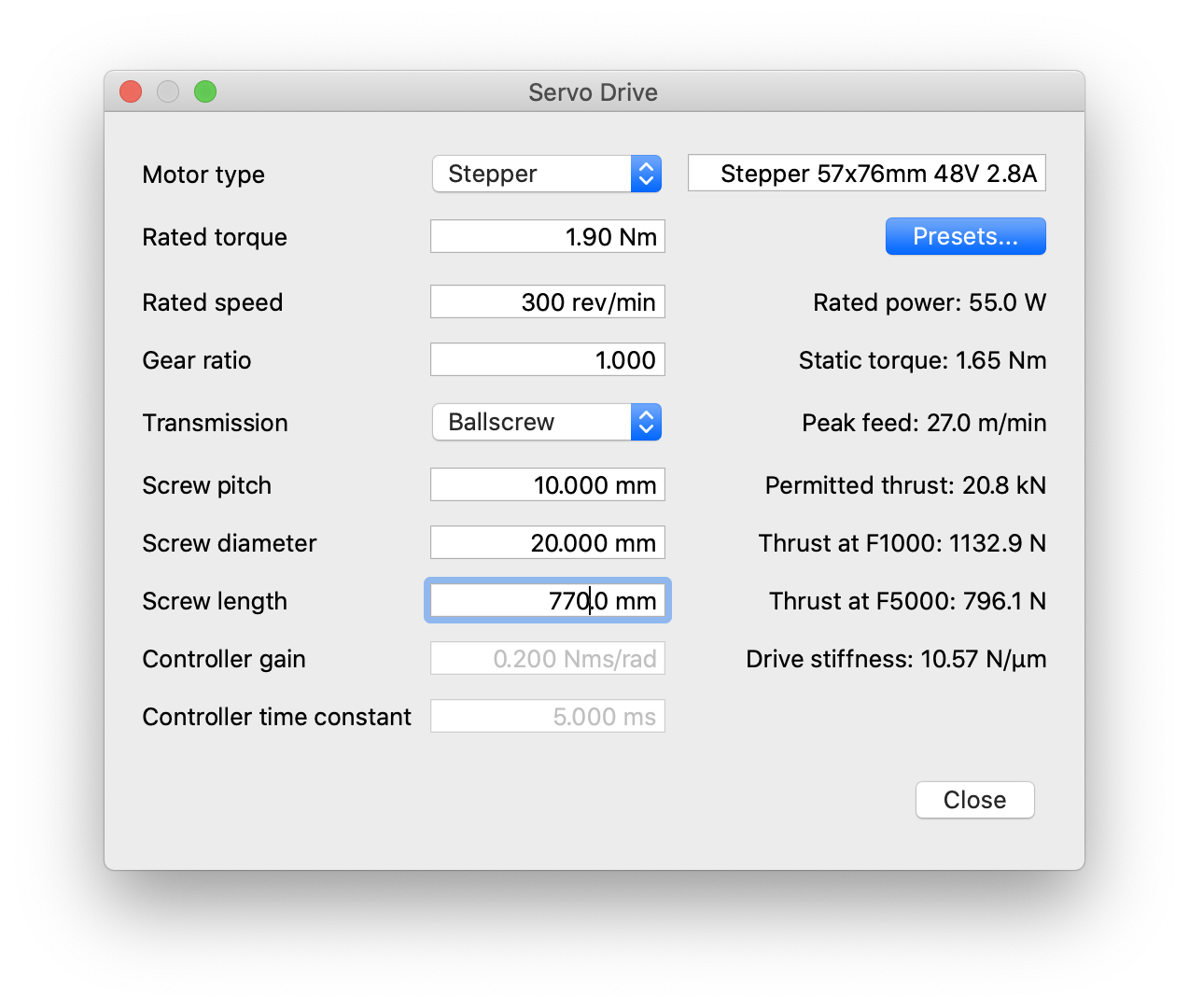 The drive calculator can be used to evaluate the static performance of a motor/transmission configuration. This can assist in identifying weak links in an existing machine or may be used to evaluate the potential benefit of modifications.
A similar calculator is opened when the linear axis drives of detailed machine models are configured (Edit - Machine - Drives). Details about the settings in the dialog can be found here.