Tool Management
Choosing a tool
Endmill geometry can have a large effect on machining forces and required torque. Selecting a suitable tool is therefore very important, and millalyzer can help to identify one.
Note
Millalyzer cannot take all possible machining conditions into account. Always check your tool selection with the manufacturer’s recommendation regarding material compatibility and maximum chip thickness. For example, millalyzer’s force and torque predictions will often favor sharp-edged endmills (large rake angles and small cutting edge radius). Such tools are very susceptible to chipping and dulling in hard materials and would therefore degrade very quickly.
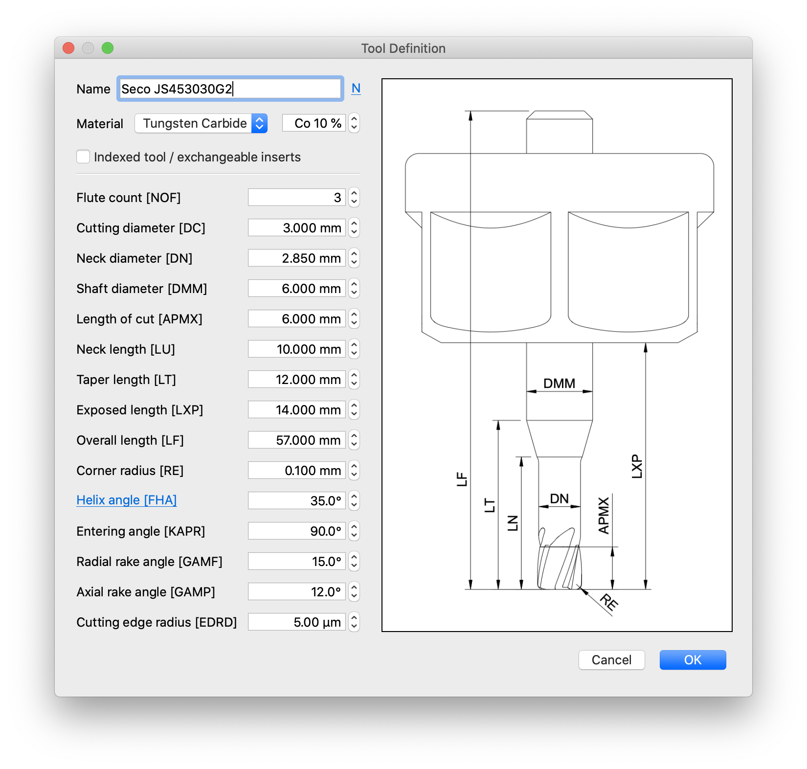 The Tools tab shows a list of currently configured tools. Millalyzer ships with built-in tool libraries, including one with vendor-supplied geoemtry data. Given the very large number of tools that are available on the market for different applications, it is very likely that the user will need to edit their own tool geometry. For this purpose there is a tool editor, shown to the right.
Tool parameter
Although there are what may appear a large number of values to configure, many only affect the structural model (tool stiffness and strength). So, if tool deflections and failure are of no interest, the values listed below Structural geometry need not be very accurate.
Other parameter values have a significant effect on cutting forces. Probably the most important value is the rake angle which many reputable tool vendors specify in their catalogue. For an explanation of the role of the rake angle, see this very accessible BBC video from 1972, or the German version.
- Cutting diameter [DC]
- Diameter of the cylindrical cutting section of the endmill.
- Flute cout [NOF]
- Number of cutting edges around the circumference. More flutes mean less space per chip; please note that millalyzer does not model chip evacuation.
- Helix angle [FHA]
- Spiral angle of the flute with respect to the tool axis. A straight flute, as in some wood routing tools, corresponds to helix angle zero. Larger helix angles (45° to 55°) are common on finishing tools that are meant to be used in side-milling with small values of radial engagement and moderate chip thickness. Smaller helix angles (20° to 35°) are used on endmills for larger engagement (or slotting) because the chips are more reliably transported out of the cut. So called down-cut endmills for wood or composites have negative helix angles in order to avoid damage/delamination of the topmost layer of a workpiece.
Some tools have more complex flute shapes, and millalyzer can account for that as well. Click on the blue link named Helix angle [FHA] in the main dialog to open a dialog for defining advanced flute settings.
- Radial rake angle [GAMF]
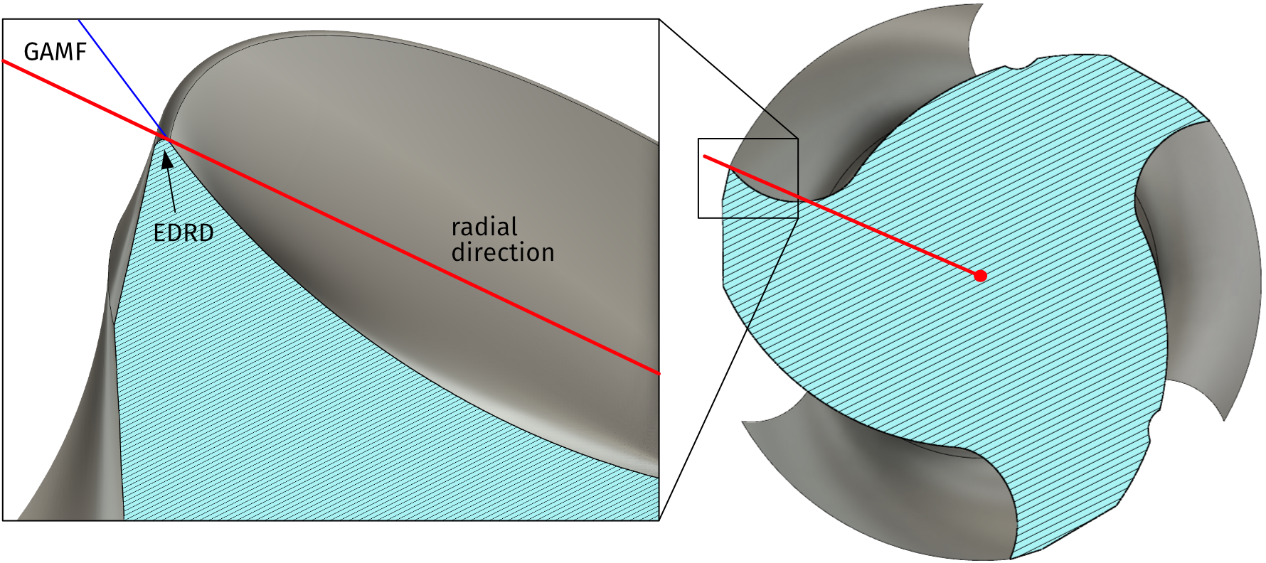
- The rake angle is a measure of the edge sharpness. A higher rake angle means a sharper tool, smaller forces, but also a more fragile cutting edge that chips easily. Many manufacturers of high-end endmills specify this value in their catalogues (Coromant, SECO, Ceratizit, WNT, Dormer-Pramet and others) using the symbol 𝛾 (gamma, or GAMF) but some do not.
 General-purpose endmills that are suitable for use in steel and other materials tend to have radial rake angles in the range 5°-10°, while tools that are advertised especially for use in aluminum are often ground to 12°-20°. See the sketch below for a definition of the radial rake angle. Large rake angles yield smaller cutting forces, but are also weaker and may break or chip sooner, especially in hard materials.
 - Cutting edge radius [EDRD]
- Set this value to zero to run the simulation for a perfectly sharp edge. Edges with very small radius tend to chip soon, while a large edge radius can make the tool last longer but also increase machining forces. High-quality endmills are often lapped or honed to create a well-defined cutting edge radius that provides good tool life for the intended material at the expense of somewhat increased cutting forces.
The combination of large rake angle and small edge radius is common in tools for plastics. Coatings, on the other hand, always increase the edge radius because they can only be applied after grinding, so that the coating thickness essentially adds to the radius. Many common commercial (PVD, arc) coatings are only 1-5 µm thick, others (CVD or PVD-SFC) lie in the range 4-18 µm.
- Entering angle [KAPR]
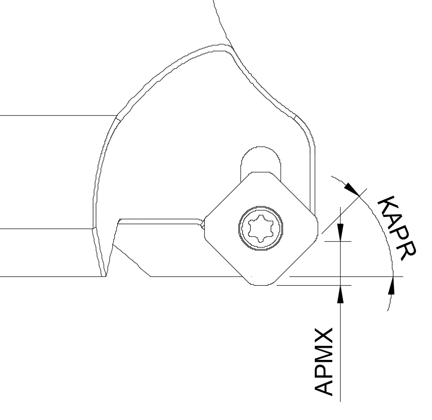 Indexed face milling cutters are often equipped with inserts that are rotated such that the cutting edge enters the material not head-on (KAPR 90°) but slanted (KAPR 10° to 45°). Reduced entering angles lead to axial chip-thinning, which can then be balanced by increased feed. However, the maximum possible axial engagement APMX also decreases with KAPR.
For tools that are marked as indexed, not solid, some further details of the insert edge geometry can be configured in a small dialog that is opened by clicking on the link “Cutting edge radius”. For an explanation, see the section on indexed tools below.
Complex flute shapes
 The default geometry defined by the properties described so far generates a regular flute pattern with polar symmetry. This means that, for a 4-flute endmill running at 6000 revolutions per minute (100 per second), the tooth impact frequency is 400 Hz; that is, the same cutting force pattern repeats exactly every 2.5 milliseconds. By changing this regular flute arrangement slightly, the regularity is broken: Flute 2 may impact 2.4 milliseconds after flute 1, followed by flute 3 at 2.6 ms after that, for example. This has the effect of shifting some of the energy that is exciting vibration in the machine to other frequencies, instead of concentrating it on a few fixed multiples of the spindle speed. When the machine, tool or workpiece fixture has a resonance close to one of the spindle harmonics, such a modified endmill can have a beneficial effect on vibration levels.
- Unequal helix angle
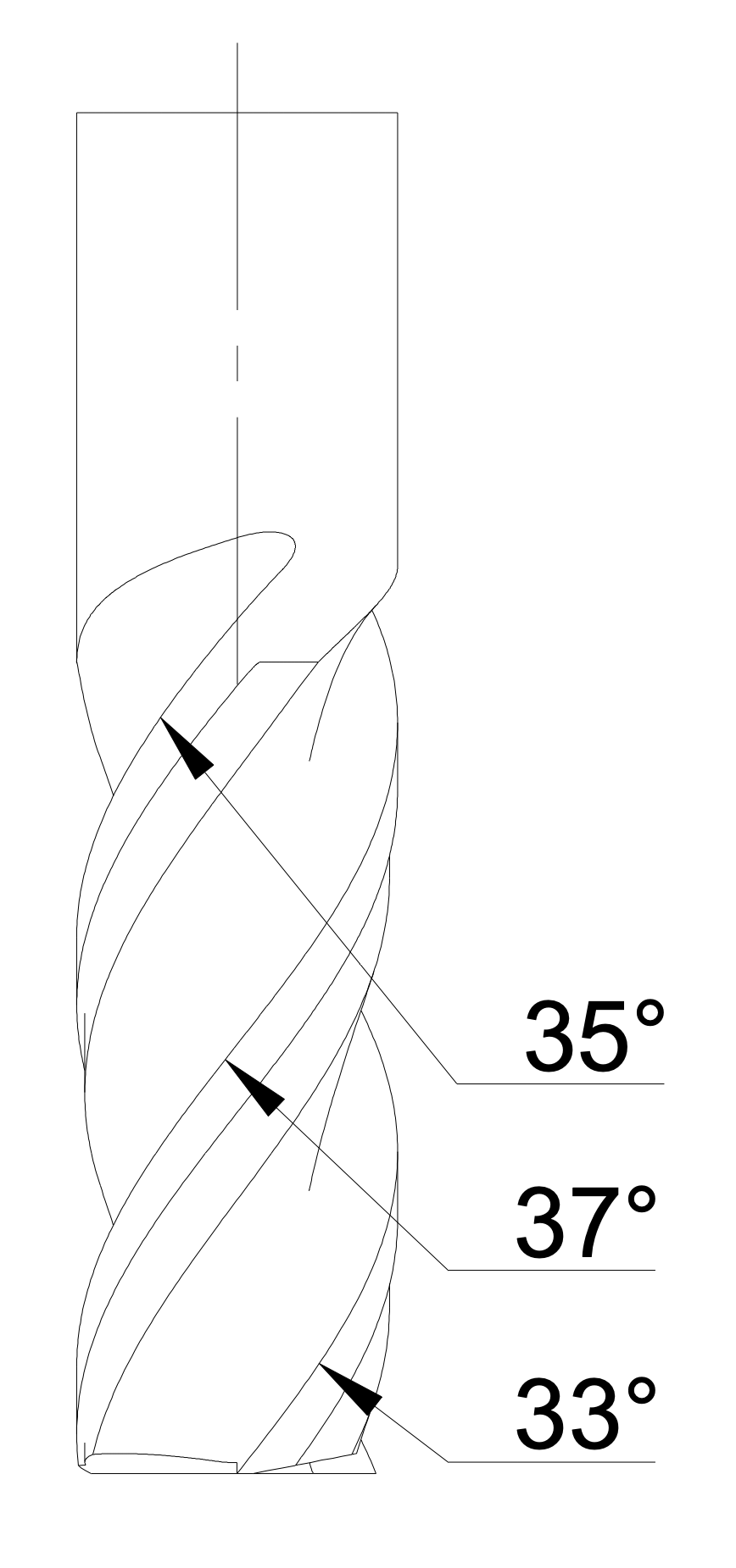 Some high-end endmills have flutes with slightly different helix angles. This can sometimes help to alleviate chatter. To define such a tool, check the box and enter the difference between the highest and lowest flute helix angle. In the picture this is 4°, which is comparatively much. With uneven helix angles, some adjacent flute pairs will converge with increasing distance from the tool tip, reducing chip space. Therefore, tools with unequal angles often have short length of cut [APMX] or they also have unevenly pitched flutes (see below). Note that millalyzer will accept unreasonably large helix angle variations, even if they are detrimental or impossible.
- Uneven flute spacing
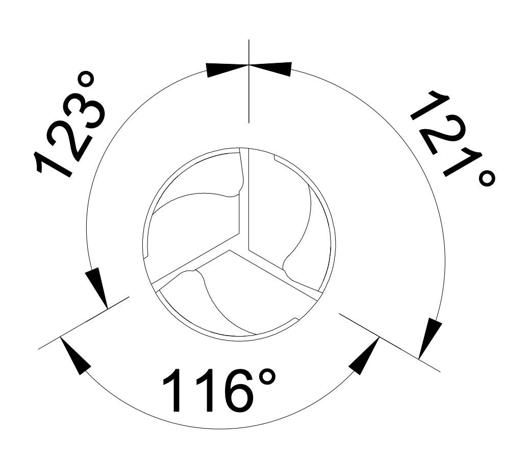 Most tools have their flutes evenly spaced around the circumference. Enable this option for tools where the flute indexing (circumferential spacing) differs. As for unequal helix angle, this feature can reduce chatter tendencies in some cases, but will reduce the width of at least one gullet. This unequal indexing has an effect on the tool tip as well, while unequal helix angles have not.
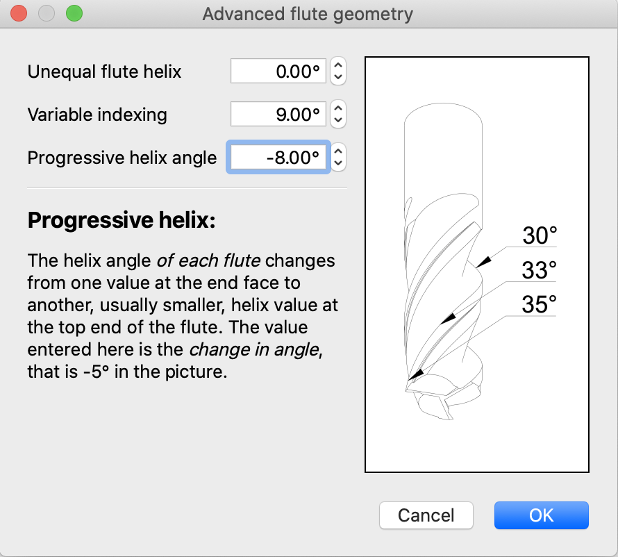
 - Progressive helix angles
- Some tools are ground such that the helix angle of each flute is larger at the tool tip than at the top end of the flute. This is called a progressive helix and can be defined by setting the change in helix angle along the flute. That is, for a helix of 35° at the tip reducing to 30° at the top end of each edge, the value to be entered would be -5°. This type of flute grinding can be applied to any length of cut. Note that progressive helix angles is not the same as the (much more common) unequal helix angles.
Structural geometry
Additional tool parameters are used to assemble a finite-element model that is used to compute how the endmill bends along its length.
- Material
- Can be tungsten carbide (HM) or high-speed steel (HSS). Carbide is a composite of very hard ceramic materials (mostly carbides and nitrides) that are sintered and infused with a Cobalt binder. Different tools use different fraction of Cobalt content, which has a strong effect on material properties. More Cobalt (up to 25%) reduces the hardness and elastic modulus, but increases toughness, while less Cobalt (down to 5%) yields a stiffer, harder material that is very brittle. Carbide in tools for cutting aluminum and plain steels often have around 10% carbide, but that can vary between manufacturers.
- Exposed length [LXP]
- This is the length of the tool sticking out of the tool-holder (stickout). For small.diameter tools, this is the single most important quantity controlling tool deflection. The value given for the endmills in the built-in collection are the minimum amounts that can be achieved; the actual exposed length is set in the operation panel.
- Detail dimensions
- Neck diameter [DN], neck [LN] and taper length [LT] are used to set the dimensions of the finite-element model. These values should be chosen correctly if tool deflection or tool stress and failure is of interest.
Indexed tools
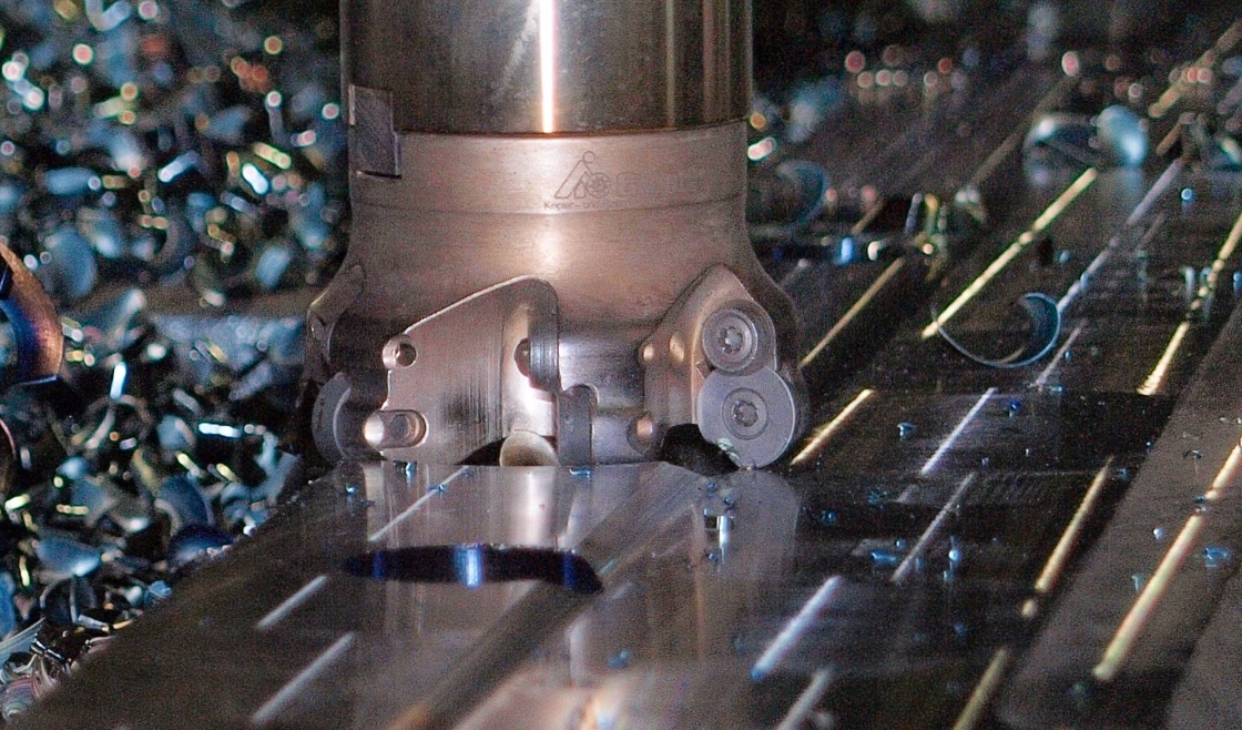 Modern tools with large cutting diameter (> 20 mm), such as face milling cutters are usually equipped with carbide inserts that can be exchanged individually when worn. Furthermore, many types of inserts have two or more usable edges which can be brought to bear by rotating and re-installing the same insert.
The cutting geometry needed for millalyzer is determined by the insert shape and the angles at which it is mounted in the tool. Unfortunately, the required data is not always published by the tool vendor. When more detailed data isn’t available, the following approximations may be used to define an approximate cutting edge geometry.
| Material class | Rake angle | Edge radius |
|---|---|---|
| P - Steel | +5° to +10° | 5 µm - 25 µm |
| M - Stainless steel | +3° to +7° | 5 µm - 25 µm |
| N - Wrought aluminium | +8° to +25° | 1 µm - 10 µm |
| S - HRSA & Titanium | -3° to 5° | 15 µm - 25 µm |
| H - Hardened steel | -20° to +3° | 15 µm - 25 µm |
In general terms, the cutting edge radius [EDRD] of inserts tends to be larger than the equivalent value of sharp-ground solid tools, which is due to the production process. High-performance inserts for aluminium or finishing operations in annealed steels are sometimes ground and polished. Such inserts can have similarly small edge radii as solid carbide tools.
- Facet width [w]
 Inserts for medium to heavy milling in steel, cast iron and hard alloys are usually equipped with a facet on the cutting edge. This is a narrow strip along the cutting edge which is either flat (zero rake) or features a lower rake angle than the main rake face.
 - Facet - Radial rake
- In the image on the right, the facet rake A is positive, but smaller than the main rake B. In many cases, the facet rake A is negative in order to produce a stronger edge that will last longer. This field in the dialog concerns the rake angle for the peripheral cutting edge, which is active during most operations such as shoulder milling.
- Facet - Axial rake
- As above, this is the facet rake angle (A), but for the axially acting cutting edge. This is the rake angle that is active for plunging motion.
Example
The Pramet SAD11E indexable shoulder mill with cutting diameter DC 25 mm has an axial insert setting angle of 5° on the tool side and a radial setting angle of -10.2°. If this tool would be used with an entirely flat insert, then these would be the rake angles as well. However, the SAD11E shoulder mill is intended for use with positive-geometry inserts, that is, inserts that are shaped to have a rather large positive rake angle themselves.
Let’s assume that this tool would be equipped with Pramet ADMX 11T304SR-MM inserts, with a main rake angle of 25°. An approximate tool definition for millalyzer would then use the following data:
| Property | Value | Comment |
|---|---|---|
| APMX | 9 mm, 0.354” | (insert spec) |
| RE | 0.4 mm, 16 thou | (insert spec) |
| EDRD | 10 µm, 0.4 thou | (approximation) |
| GAMF | 14.8° | 25° - 10.2° |
| GAMP | 30° | 25° + 5° |
| FHA | 13° | 8° + 5° |
| KAPR | 90° | (tool spec) |
| NOF | 3 | (tool spec) |
| Facet width | 130 µm | (insert spec) |
| Facet radial rake | 0.8° | 11° - 10.2° |
| Facet axial rake | 16° | 11° + 5° |
In the sums, the first value is from the insert specification and the second is the setting angle on the tool side. The insert contribution to the helix angle FHA (8°) is unfortunately not specified by the manufacturer but estimated here from approximate measurements.