Machine Limits
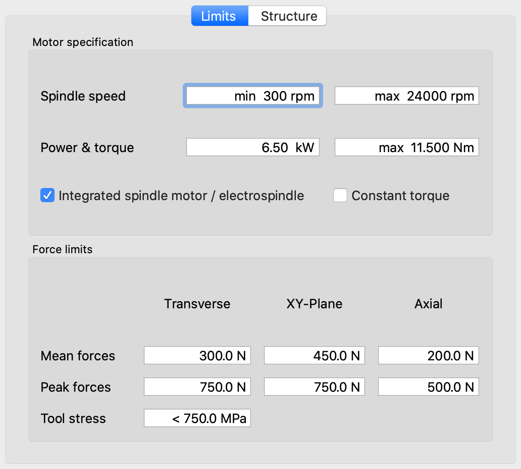 The machine limit settings are used to define the capabilities of the machine. These settings do not directly influence the milling force predictions, but are relevant for recommendation of AE and AP values within machine constraints.
The recommendation and optimization procedures accounts for limits on torque (at the current spindle speed), mean and peak forces and tool stress level.
Spindle torque
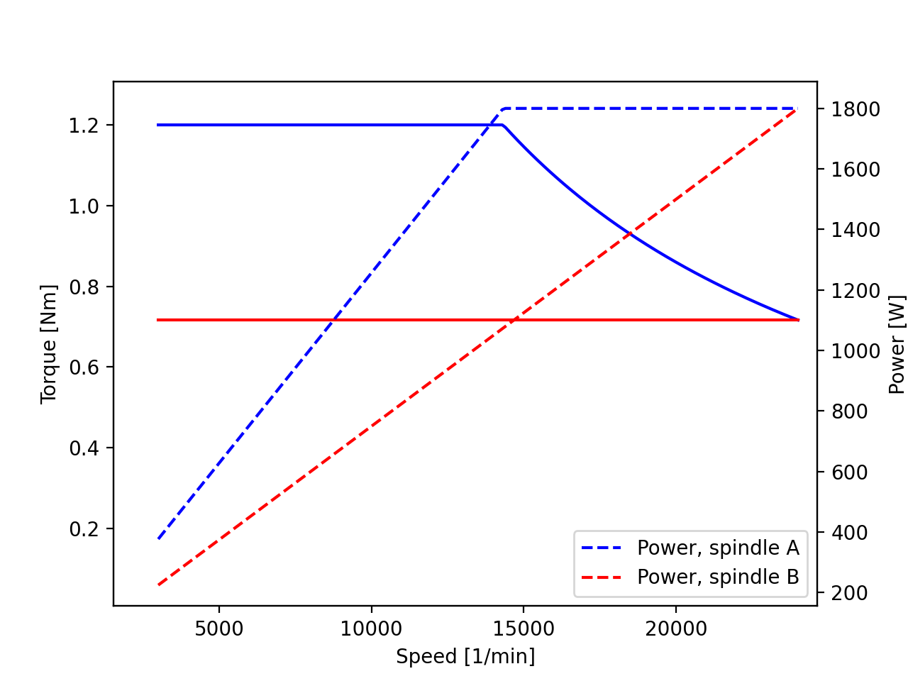 An approximate model is used to describe the spindle torque as a function of commanded speed: the torque is assumed constant at the specified maximum value for low speeds until the power resulting from the product of torque and speed reaches the given nominal power, from which point on the torque falls inversely with speed to maintain that constant power until the maximum speed. The diagram to the right shows the torque and power curves for two spindles A and B configured with the same peak power but different maximum torque values as in the table below.
| Limit | Spindle A | Spindle B |
|---|---|---|
| Power | 1.8 kW | 1.8 kW |
| Torque | 1.2 Nm | 0.716 Nm |
In many cases, the torque profile of modern spindles is strongly influenced by the performance and characteristics of the variable-frequency drive (VFD) and the cooling system. Short term loading at reduced duty cycles (e.g. S6-15%) may allow for substantially higher power and torque than continuous operation; configure the limits in this dialog according to the duration of the machining operation that is to be performed.
Force and stress limits
Recommendations for machining parameters use the limits below to find values that are within the capabilities of a machine and will not overload the milling cutter itself.
- Transverse
- This is the maximum allowed force that is pushing the tool into or away from the workpiece, perpendicular to feed. Limit this value to keep lateral tool deflection in check, which can improve surface finish quality.
- XY-Plane
- The in-plane force is the vector sum of transverse and feed-direction force. Therefore, it is this force that loads the spindle bearings in the radial direction. Furthermore, this is also the largest force that the drives for the machine axes will have to sustain.
- Axial
- These loads act parallel to the spindle shaft and therefore load the bearings axially. CNC routers are often equipped with milling motors that do not have angular-contact bearings which can take these loads. Plain single-row deep-groove ball bearings have a relatively low axial load rating; therefore the axial load limit should be set rather conservatively in this case. In larger spindles, angular-contact ball bearings are typically axially preloaded. It is advisable to keep axial loads well below the preload level in this case.
- Tool Stress
- When using small-diameter endmills on large machines, tool stress is the limiting parameter, because spindle torque and machine feed forces can easily break such tools. Set this limit to a low value to prevent AE/AP recommendations that strain the endmill itself very much. In any case, this limit should incorporate a significant safety margin with respect to the nominal strength of the tool material.