Machine Model
A model for the machine structure is needed to solve for dynamic tool motion. The settings described in the following sections have no influence on static solutions, meaning that users of millalyzer-static can ignore this page.
Two types of machine models can be defined. A simplified model, described with just a few parameters, can serve as an approximation when nothing more is known. When available, a detailed model derived from experimental data or a finite-element analysis can provide much better accuracy in predicting dynamic motion. Millalyzer comes with three detailed models for different machines built-in; these can also serve as a starting point for modifications.
Note
As a rule of thumb, the simplified model is often (but not always) more rigid than a detailed model that includes the same spindle dimensions. This means that chatter predicted with a simplified model is unlikely to disappear with a more detailed structural representation.
Simplified model
 When selecting the simplified model, millalyzer will build a finite-element model for the tool/endmill and spindle axis, that is supported by bearings with configurable stiffness. That is, the dynamic solution will in this case account for bending and torsion of the rotating components shown in the drawing to the right, but not simulate motion of the stationary machine frame or workpiece.
Spindle dimensions
When the simplified model is selected, there are only a few values to define. This makes it quick and easy to setup a simplified spindle model, but also limits the level of accuracy that can be achieved. For small or high-RPM spindles (D < 20 mm), the simple model may be able to capture much of the dynamic flexibility of the system.
- Spindle diameter
- This is the outside diameter D of the spindle shaft. Even a small increase in diameter makes the shaft a lot less flexible and a little heavier, both of which can reduce oscillations. In case the diameter is not accessible for measurements, it may be possible to draw conclusions based on the diameters of bearings which are sometimes advertised. The table below shows the inner bearing diameter along with axial bearing stiffness values for preload level C.
- Bearing positions
- The nose bearing location L1 is the distance between the end of the spindle shaft (where the endmill is inserted or the toolholder attaches) and the center of the most forward bearing, while the tail bearing location L2 is the distance to the rearmost bearing. In most cases, the rear bearing location is some distance away from the rear end of the spindle.
- Bearing stiffness
- The spindle shaft is typically mounted in two (pairs of) angular contact bearings. Depending on the preload, these bearings act like (very stiff) springs that allow a small degree of shaft movement. For the common ball contact angle of 15 degree, the radial stiffness of angular contact bearings is approximately 3 to 4 times larger than the axial stiffness given in the table below. Bearing stiffness increases with axial preload. However, a higher preload also reduces the maximum permitted spindle speed (RPM).
| Bearing | 7002 | 7003 | 7004 | 7005 | 7006 | 7007 | 7008 |
|---|---|---|---|---|---|---|---|
| Inside diameter | 15 mm | 17 mm | 20 mm | 25 mm | 30 mm | 35 mm | 40 mm |
| Axial stiffness | 31 N/um | 35 N/um | 42 N/um | 46 N/um | 55 N/um | 64 N/um | 73 N/um |
- Direct drive
- For spindles that are driven directly, that is, where the spindle axis is the rotor of an electric motor (‘electrospindle’), an approximation for of rotor mass and stiffness are added automatically. This can have a beneficial effect in the case of small-diameter spindle axle and large rotor (powerful motor).
Presets
When detailed spindle dimensions are not available, one of the predefined settings can be used as a starting point. It is, however, strongly recommended to adjust at least those dimensions which are readily available. The nose bearing location, for instance, can often be measured or estimated from measurements with reasonable accuracy, and can have a considerable effect on chatter. Bearing stiffness values should not be a dominating factor for a well-designed spindle, but may become relevant for lower quality products or high-speed (> 30 000/min) spindles that require reduced preload.
Detailed model
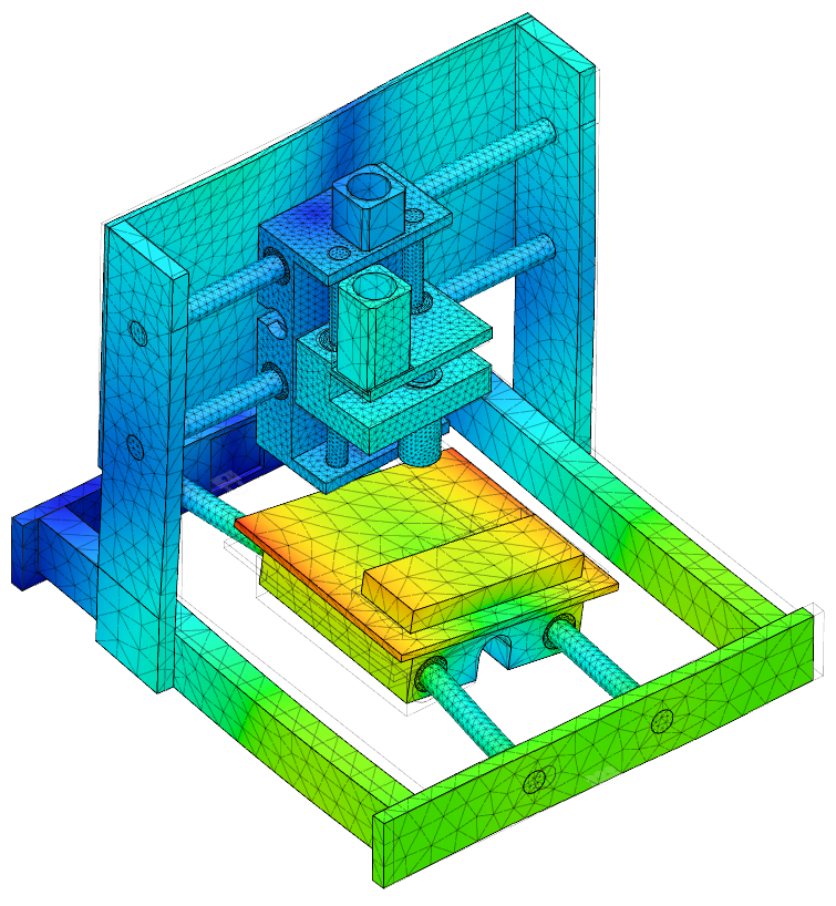 In contrast to the simple approach, a detailed model includes a representation of the entire machine frame and workpiece fixture, so that the dynamic simulation can correctly account for the relative motion of tool, toolholder, spindle and frame relative to the workpiece material. Such a model is based on a modal subspace representation for the machine/workpiece structure that can be derived from a finite-element model (as the one shown here) or from experimental modal analysis.
As the amount of information needed to define such a model is rather large, models of this type must be loaded from files. Three models are integrated in millalyzer and are therefore always available even if you do not have access to a custom model for your machine.
The built-in models are for
- a modest vertical machining center with a machine frame mass of 1.8 tons (4 000 lbs);
- a moving-gantry table router as it is used in woodworking (140 kg, 310 lbs);
- a small desktop milling machine (20 kg, 44 lbs),
- a medium-sized industrial gantry machine of about 20 tons, with a work envelope of about 3-by-1-by-1 meter.
where the mass given is for the load-carrying structure only. More models may be added in future versions of millalyzer.
Note
Setting up a detailed model requires either experimental data (modal testing) or 3D geometry of the machine frame. If you need assistance defining a dynamic model for specific machine, please contact us for support.
Toolholder

Most milling machines are equipped with a mechanism for tool changes, which means that the cutting tool is not directly mounted to a fixed spindle chuck but into a separate toolholder that fits into a standard interface at the spindle side. From the perspective of dynamic simulations, the important aspect is that such toolholders are available with very different dimensions that can have a strong influence on dynamic behavior. As an example, the image above shows a standard long-reach product which reduces the radial stiffness (tool tip) of the builtin VMC model from 7.6 N/µm to 1.7 N/µm.
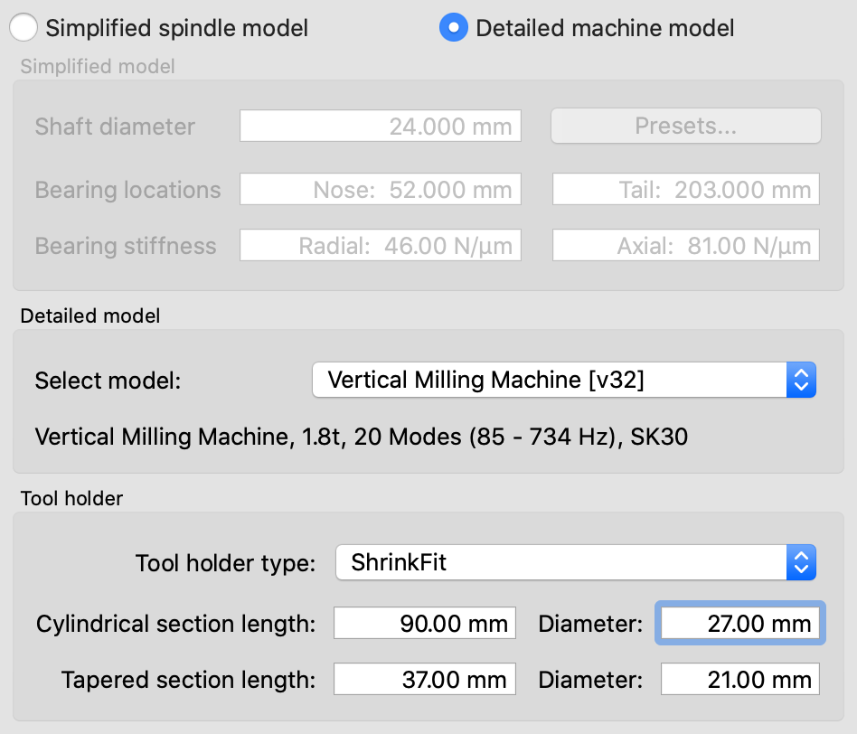
To define this type of toolholder, modify the settings in the machine properties dialog as in the screenshot to the left. While the spindle-side interface is defined in the machine model file and therefore fixed, the tool-side interface can be selected from the drop-down menu. When, for instance, an ER32 chuck is selected, the diameter and mass of the part is automatically accounted for - there is no need to enter additional data. For shrink-fit (or similar) toolholders such as the one above, you can freely define the dimensions to fit the product in question.
The following toolholder types can be selected:
- Shrink-fit or hydraulic clamping, configurable dimensions
- Short ER8/11/16/20/25/32/40 chucks, fixed dimensions
- Short facemill arbors with 16/22/27/32 mm pin diameter
- Screw-in arbors M8/M10/M12/M16 for modular endmills
- Direct (e.g. proprietary) tool-spindle interface
Frame FRF
For detailed machine models, an additional tab is available in the machine editor dialog. This tab shows the frequency response functions (FRF) of the selected machine frame model, expressed as dynamic compliance values over frequency. FRFs are useful because they can be determined experimentally as well.
FRFs are one way of characterizing the displacement response of a structure to dynamic loading. When a structure is loaded by a sinusoidal (oscillating) force, it will (within limits) respond with a sinusoidally varying displacement with a certain amplitude and phase shift. Both amplitude and phase shift of this response change with the frequency of the applied load. The FRF plot shows the ratio of displacement to applied force as a function of frequency. The value at zero frequency is simply the static compliance (that is, the inverse of stiffness).
The exact shape of an FRF depends on where the load is applied and where the displacements are recorded. In millalyzer, displacements are determined for the same locations where the loads are applied. The direction of the applied force vector can be freely selected, because many machines have a strong directional stiffness variation.