Dynamics
The features described on this page are available in the millalyzer dynamic product only.
Whenever milling forces are computed (Solve button) in millalyzer dynamic, a time-domain simulation is started in the background. Switch to the Simulation tab to review progress and results.
What is chatter?
There is always some degree of flexibility in a tool, toolholder, spindle, machine frame, workpiece and fixtures. Often it is possible to reduce this flexibility to very small values (albeit never to zero), but sometimes a less rigid setup is unavoidable. Cutting forces that act on tool and workpiece therefore lead to small elastic displacements. Usually, the magnitude and direction of these forces change with time, possibly several times per tool revolution.
As the varying forces act on the tool and workpiece, they will incur a small amount of motion relative to each other. This means that the cutting conditions (engagement, chip thickness) are no longer what they would be in a perfectly rigid machine, but change in time. Obviously, different conditions lead to different cutting forces, so that there is mutual interaction between forces and relative motion.
Such an interaction need not be problematic. For instance, when climb-cutting, the tool will be pushed away from the workpiece. This can be all that happens: the relative displacement leads to reduced lateral engagement, thus lower cutting forces and a new equilibrium may develop in this slightly deformed state. A loss in accuracy (oversized part after the cut) would be the only consequence.
It is however possible that this interaction causes an undesirable oscillation with increasing amplitude. One common mechanism that can cause this is regenerative chatter, where one flute is displaced away from the workpiece, cuts too little material and therefore leaves a tiny bulge in the surface. The next flute may hit the stock while the tool is oscillating back towards the workpiece, and it now must engage not only the nominal amount but also the extra material left by the previous flute. Clearly, cutting forces will be higher this time, leading to larger displacements and thus to an oscillation with increasing amplitude.
This is the mechanism that is modelled by millalyzer.
Recommended usage
The main purpose of the dynamic simulation is to warn for conditions that would lead to severe chatter. More details are given below, but in general, the procedure to check for chatter involves these steps:
-
In the upper window, look out for oscillation amplitudes that increase in time. If there is violent growth so that the simulation stopped halfway through, you are very likely to see unacceptable chatter - perhaps even a snapped endmill.
-
Should amplitudes increase visibly, but not catastrophically during the default 12 revolutions, increase simulation time to maybe 30 to see at which level the vibration stabilizes.
-
A chatter index value approaching or exceeding 1.0 indicates substantial chatter even if the amplitudes are not very large (yet).
-
Check the peak displacement display panel to see whether the reported tool tip displacements are in an acceptable range for the intended operation. A finishing pass will not yield acceptable results with tool vibrations of 50 µm, but for a roughing pass, that may be perhaps still be sufficient.
Simulation
The simulation starts with the cutter entering the workpiece material and proceeds for a number of tool revolutions. Since the cutting forces will slightly bend both endmill and spindle shaft, the cutting flutes move a little with respect to the workpiece. This, in turn, changes the thickness of the chips cut by the engaged flutes and leaves either a dent or a small bump in the freshly cut surface. The next flute that enters the cut will therefore encounter a larger or smaller effective chip thickness than it would in a perfectly rigid setup. This interaction can both be stable with very small oscillations, or it can produce violent chatter that leaves behind a badly marred surface and may even cause tool failure. When side-milling, the oscillation will eventually stabilize in all but the most extreme situations (tool failure). For sufficiently large endmill deflection, more and more of the flutes will loose contact with the workpiece during a part of the oscillation, when the tool is bending away from the cut. This has the effect of reducing the effective radial engagement and therefore limits the amplitude.
The magnitude and stability of this oscillation depend on
- Milling parameters (AE, AP, HEX, cutting speed);
- Material properties;
- Tool and spindle flexibility and mass;
- Rigidity of the machine frame;
- Workholding.
Changing any of these can make a significant difference. Millalyzer dynamic accounts for the first three factors at the time of writing.
Results
Typically, a simulation of about 20 revolutions takes a few seconds to complete. Under very unfavorable circumstances, the oscillation can quickly grow to amplitudes that would probably lead to tool failure - in this case the simulation is stopped prematurely.
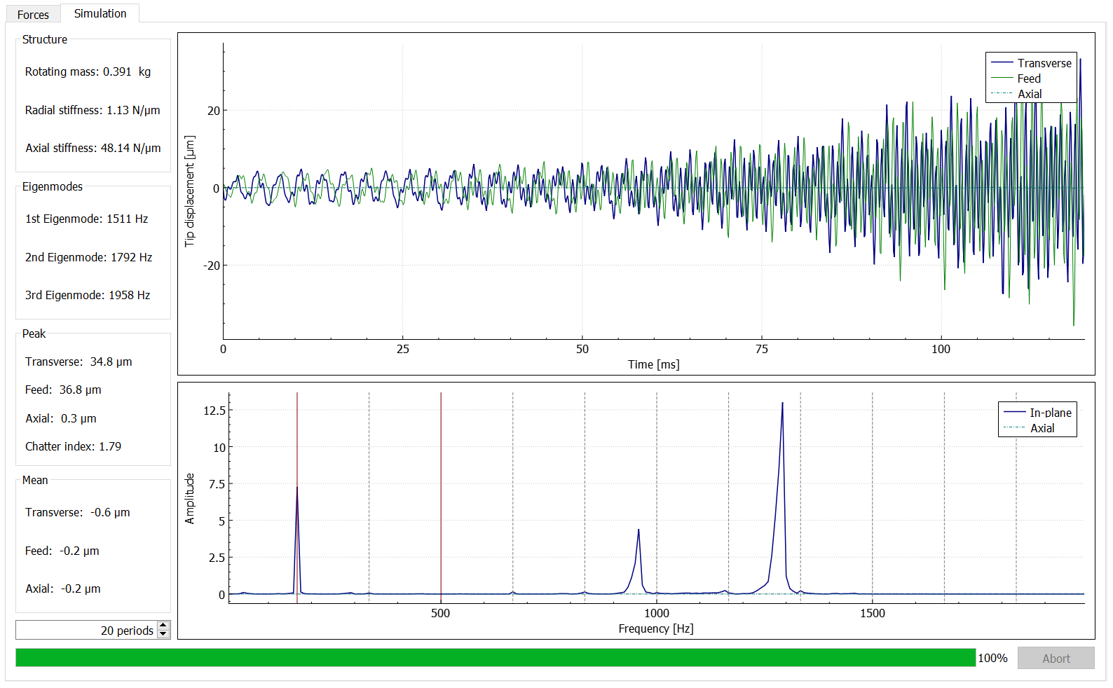
Once a simulation is finished, the motion of the endmill tip is shown in the upper diagram as a function of time. The coordinate system used here moves with the tool but does not rotate, as illustrated in the section In-Depth. In most cases, this diagram shows fairly clearly
- wether the vibration amplitude will grow with time (unstable process), and
- what the amplitude of oscillation is.
Note
Even if a process is perfectly stable, lack of rigidity or unfavorable conditions can mean that the tool vibrates with considerable amplitude, 50 µm or more. This may be acceptable for a heavy roughing pass, but will most likely yield a finish with pronounced tool marks and may damage the endmill.
The lower diagram shows the frequency-domain decomposition of the tip displacement, which can be useful in identifying the cause of excessive vibration.
Next to the diagrams, some additional information is displayed in text form. In the first section at the top, there is mass and computed stiffness for the spindle/tool combination. Note that this (as of now) does not include the effect of machine frame deformation. Stiffness values are given with respect to loads acting on, and deflections measured at, the tool tip. Next to the stiffness data, the rotating mass of the spindle model is given along with the first three eigenfrequencies of the tool-spindle-bearing system, assuming a rigid machine frame.
Below that, a summary of displacement data is shown. Peak displacements are the maximum absolute values that are instantaneously reached in the different directions, while the mean values are a measure of the average displacement that occurs over the simulated time. Among these values, the mean transverse displacement indicates the accuracy that could be expected at best. For the example in the picture (climb milling), the tool tip is displaced laterally 26 µm away from the workpiece on average, while the maximum transverse displacement is over 150 µm, i.e. substantial chatter marks.
Chatter prediction
There is no perfect single metric of chatter that can always be relied on, but there are several useful indicators. Among the peak displacement display, there is a value called chatter index. This is computed from frequency-domain data shown below.
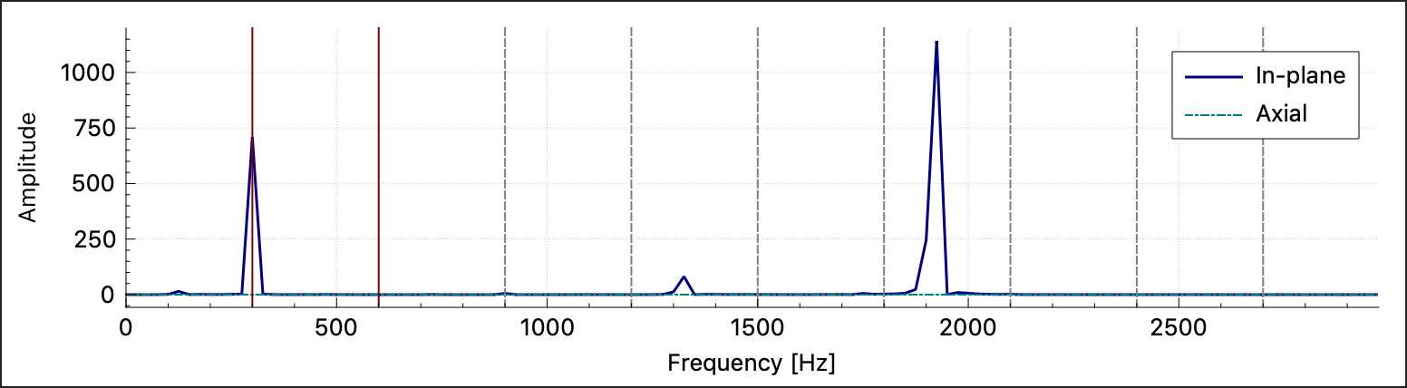 As can be expected, the displacement signal carries much energy at the frequency that corresponds to the spindle revolution (here: 300 Hz) and its harmonics, among them the tooth-passing frequency. In this example, there is also a strong contribution at around 1900 Hz, that is not a multiple of the spindle frequency. In other words, there is a strong oscillation at a frequency where we do not expect one - this is a good indication of chatter.
The chatter index is simply the amplitude of the highest peak that occurs at an unexpected frequency, divided of the amplitude of the highest of the expected peaks. This indicator should be low, at least below 0.3, for the operation to be regarded free from chatter.
Caveat
As mentioned previously, chatter is a fairly complex phenomenon. Millalyzer strives to include the most relevant effects in order to give a useful indication, but there are many dependencies that are not modelled at this time. These can both cause chatter when millalyzer predicts none, and stabilize cutting conditions which appear disastrous in the simulation.