In Depth
Coordinate system
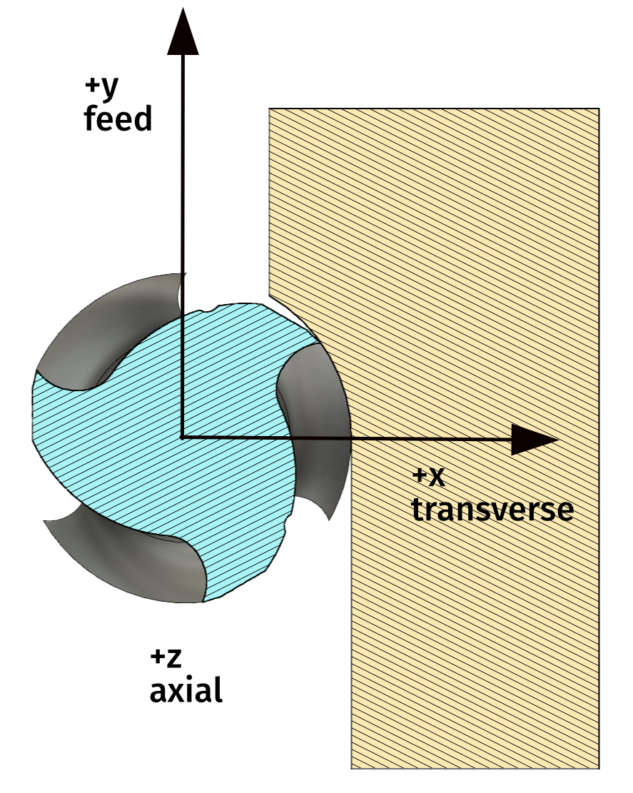 Because millalyzer is intended to predict tool loads, the coordinate system shown to the right is used. Force directions are:
- Positive x is a transverse force that pushes the tool sideways into the workpiece;
- Positive y points in the direction of tool motion, i.e. this force pulls the tool forward into uncut material;
- Positive z pushes the tool into the spindle.
This means that, for the common case of climb milling with AE less than D/2, the expected forces are negative x (endmill pushed sideways away from the workpiece), positive y and negative z (endmill pulled out of the tool-holder). Displacements are shown with the same sign convention.
Feed and chip thickness
When controlling loads, uncut chip thickness (HEX, chipload) is an important factor. When the radial engagement is AE = DC/2 or larger, then the chip thickness is identical to feed per tooth (FZ).
Cutting tool manufacturers commonly recommend feed-per-tooth values (FZ). Quite often, the feed recommendations vary with relative radial engagement AE/DC, for example this rather detailed table taken from the Dormer-Pramet catalog (tool category C, diameter 6 mm):
| AE/DC | Recommended FZ | Corresponding HEX |
|---|---|---|
| 0.05 | 108 µm | 47 µm |
| 0.08 | 86 µm | 47 µm |
| 0.15 | 64 µm | 46 µm |
| 0.30 | 46 µm | 42 µm |
| 0.60 | 35 µm | 35 µm |
Apparently, these detailed recommendations just boil down to a chipload of about 47 µm for small radial engagement, reduced a little for conditions with larger engagement angles. This is the reason that the chipload can be used as a controlling variable in millalyzer.
Millalyzer will issue warnings in the Status field whenever the uncut chip thickness becomes large relative to the tool diameter, as that could indicate a risk for insufficient chip evacuation. Likewise, there will be a warning for built-up edges (BUE) when cutting aluminum and one indicating a risk for rubbing when HEX is very small. These warnings are based on empirical relations and have no effect on the remaining computation.
Lubrication
Lubrication has a strong effect on local friction properties. By default, millalyzer assumes dry machining, that is with air blast only. Optionally, the user can specify emulsion (flood) lubrication, which assumes that the optimal lubricating effect (reduction of friction) is achieved throughout the entire cut. Mist lubrication or MQL will likely yield results between these two extremes. Coatings can have an effect on friction as well; here, millalyzer assumes uncoated tools when used in aluminum and TiAlN-coated tools (standard) when specifying steel as a workpiece material.
Computational model
A tool in millalyzer is represented by two models: An edge-element model that provides a distribution of cutting forces, and a finite-element model that is loaded with these forces to determine displacements or motion. Typically, each cutting edge is subdivided into a few hundred edge elements. The cut geometry is analyzed to generate an oblique-cut model for each element, which is then iteratively solved using a temperature, strain and rate-dependent flow-stress relation for the workpiece material. For each tool rotation angle, the entire procedure is repeated for each edge element and the integrated forces over a full revolution are displayed. Torque is computed by summing the tangential contributions of each edge element multiplied by its effective radial distance from the tool axis. Applying the linear force distributions to the finite-element model of the tool structure yields a longitudinal distribution of displacements. Only the displacement of the tool tip is shown in the user interface.
Simulating machine dynamics
The finite-element model of the structure includes the endmill itself, the spindle shaft and the main spindle bearings in idealized form. Additional non-structural mass is added to the shaft between bearings to account for the rotor windings.
Displacements are computed by integrating the motion of this finite-element model of the rotating structure in time using a second-order accurate implicit Runge-Kutta method of Owren and Simonsen. Cutting forces are computed in a tightly coupled form, which means that at each time step, the forces due to the cutting edges engagement are consistent with the instantaneous deformation. This integration approach is computationally expensive, but numerically stable whenever the system is stable.
At the time of writing, the user interface does not provide means to define a structural model of the stationary (non-rotating) part, namely the machine frame beyond the spindle and the work-holding fixtures. Obviously, the flexibility and mass distribution of these elements can have a decisive effect on the machining result; unfortunately however, modeling these parts usually requires a structural representation that is specific for a particular type of machine and workpiece. This makes it difficult to define a common user interface. Should you be interested to include such models for a particular class of machines, please do not hesitate to contact us.
Nevertheless, chatter can occur even in rather rigid machine frames and with perfect work-holding, and this type of chatter is predicted by millalyzer dynamic. The main reason for this is that the machine frame structure that contains the rotating structure of the spindle is comparatively heavy and the flexibilities of the frame rather small. Even if the combination results in a system with eigenfrequencies in the relevant range, this part of the structure still requires large forces to be excited at frequencies that are relevant for chatter.
References
[1] Altintas, Y. Manufacturing Automation: Metal Cutting Mechanics, Machine Tool Vibrations, and CNC Design. Cambridge University Press, 2012.
[2] Oxley, P. L. B. The Mechanics of Machining : An Analytical Approach to Assessing Machinability. Ellis Horwood, Chichester, NY, 1989.
[3] Lee, E. H., and Schaffer, B. W. “Theory of Plasticity Applied to the Problem of Machining.” Journal of Applied Mechanics, Vol. 18, 1951, pp. 405–413.
[4] Johnson, G. R., and Cook, W. H. “A Constitutive Model and Data for Metals Subjected to Large Strains, High Strain Rates and High Temperatures.” Proc. 7th Int. Symp. Ballist., Vol. 21, 1983, pp. 541–547.
[5] Waldorf, D. J., DeVor, R. E., and Kapoor, S. G. “A Slip-Line Field for Ploughing During Orthogonal Cutting.” Journal of Manufacturing Science and Engineering, Vol. 120, No. 4, 1998, pp. 693–699. https://doi.org/10.1115/1.2830208.
[6] Fu, Z., Yang, W., Wang, X., and Leopold, J. “Analytical Modelling of Milling Forces for Helical End Milling Based on a Predictive Machining Theory.” Procedia CIRP, Vol. 31, 2015, pp. 258–263. https://doi.org/10.1016/j.procir.2015.03.013.
[7] Abouridouane, M., Klocke, F., Lung, D., and Veselovac, D. “The Mechanics of Cutting: In-Situ Measurement and Modelling.” Procedia CIRP, Vol. 31, 2015, pp. 246–251. https://doi.org/10.1016/j.procir.2015.03.048.
[8] Özel, T., and Zeren, E. “A Methodology to Determine Work Material Flow Stress and Tool-Chip Interfacial Friction Properties by Using Analysis of Machining.” Journal of Manufacturing Science and Engineering, Vol. 128, 2006, pp. 119–129. https://doi.org/10.1115/1.2118767.
[9] Lesuer, D. Experimental Investigations of Material Models for Ti-6AL4V and 2024-T3. Publication UCRL-ID-134691. Lawrence Livermore National Laboratory, 1999.
[10] Seidt, J. D., and Gilat, A. “Plastic Deformation of 2024-T351 Aluminum Plate over a Wide Range of Loading Conditions.” International Journal of Solids and Structures, Vol. 50, 2013, pp. 1781–1790. https://doi.org/10.1016/j.ijsolstr.2013.02.006.
[11] Laakso, S. “Heat Matters When Matter Heats – the Effect of Temperature-Dependent Material Properties on Metal Cutting Simulations.” Journal of Manufacturing Processes, Vol. 27, 2017, pp. 261–275. https://doi.org/10.1016/j.jmapro.2017.03.016.
[12] Brar, N. S., Joshi, V. S., and Harris, B. W. “Constitutive Model Constants for Al7075‐T651 and Al7075‐T6.” AIP Conference Proceedings, Vol. 1195, No. 1, 2009, pp. 945–948. https://doi.org/10.1063/1.3295300.
[13] Yibo, P., Gang, W., Tianxing, Z., Shangfeng, P., and Yiming, R. “Dynamic Mechanical Behaviors of 6082-T6 Aluminum Alloy.” Advances in Mechanical Engineering, Vol. 5, 2013. https://doi.org/10.1155/2013/878016.
[14] Chen, X., Peng, Y., Peng, S., Yao, S., Chen, C., and Xu, P. “Flow and Fracture Behavior of Aluminum Alloy 6082-T6 at Different Tensile Strain Rates and Triaxialities.” PLOS ONE, Vol. 12, No. 7, 2017, pp. 1–28. https://doi.org/10.1371/journal.pone.0181983.
[15] Valencia, J.J. and Quested, P.N. “Thermophysical Properties.” ASM Handbook, Vol. 15, 2008, pp. 468–481.
[16] Korkmaz, M.E. and Günay, M. “Finite Element Modelling of Cutting Forces and Power Consumption in Turning of AISI 420 Martensitic Stainless Steel.” Arabian Journal for Science and Engineering, Vol. 43, 2018, pp. 4863–4870. https://doi.org/10.1007/s13369-018-3204-4.
[17] Xu, D., Feng, P., Li, W. and Ma, Y. “An improved material constitutive model for simulation of high-speed cutting of 6061-T6 aluminum alloy with high accuracy” The International Journal of Advanced Manufacturing Technology, Vol. 79, 2015, pp. 1043–1053. https://doi.org/10.1007/s00170-015-6888-6.
[18] Vural, M., Rittel, D., and Ravichandran, G. “Large Strain Mechanical Behavior of 1018 Cold-Rolled Steel over a Wide Range of Strain Rates” Metallurgical and Materials Transactions A, Vol. 34A, 2003, pp. 2873–2885.
[19] Becze, C.E. “A Thermo-Mechanical Force Model for Machining Hardened Steel”, PhD Thesis, McMaster University, Hamilton, Ontario, August 2002
[20] Green, D.W., Winandy, J.E., Kretschmann, D.E. “Mechanical Properties of Wood”, in Wood handbook — Wood as an engineering material, Gen. Tech. Rep. FPL–GTR–113, Department of Agriculture, Forest Products Laboratory, Madison, WI. 1999.
[21] Laakso, S.V.A., Johansson, J., Johansson, D., Schultheiss, F., Ståhl, J.E. "Multi-objective testing of different brass alloy components for DFM", Procedia CIRP, Vol. 81, 2019, pp.127-132
[22] Agirre, J., Erice, B., Abedul, D., Saenz de Argandoña, E., Otegi, N., Galdos, L. "A Laboratory-Scale Instrumented Forging Hammer as an Intermediate Strain Rate Testing Device", DYMAT 2021 - 13th International Conference on the Mechanical and Physical Behaviour of Materials under Dynamic Loading, EPJ Conferences, Vol. 250, 01002 (2021), doi:10.1051/epjconf/202125001002
[23] Weber, A. "Magnetostriktive Schnittkraftmessungen beim Holzfräsen", Holz als Roh- und Werkstoff, (20)12, 1962, pp.486-492
[24] Iskra, P. and Hernández, R.E. "Analysis of cutting forces in straight-knife peripheral cutting of wood.", Wood and Fiber Science, (44)2, 2012, pp.134-144
[25] F. Klocke Fertigungsverfahren 1: Zerspanung mit bestimmter Schneide, 9. Auflage 2018, Springer Verlag, doi:10.1007/978-3-662-54207-1
[26] E.J.A. Armarego, D. Premenik, A.J.R. Smith, R.E. Whitfield: "Forces and Power in Drilling", Journal of Engineering Production, 6:149-174, 1983
[27] J. Saelzer, B. Thimm, A. Zabel: "Systematic in-depth study on material constitutive parameter identification for numerical cutting simulation on 16MnCr5 comparing temperature-coupled and uncoupled Split Hopkinson pressure bars", Journal of Materials Processing Tech., 302(2022) 117478 doi:10.1016/j.jmatprotec.2021.117478